Catheter

a catheter and tube technology, applied in the field of catheters, can solve the problems of bending the tube, restricting the use of gastric/jejunal feeding tubes or catheters,

Inactive Publication Date: 2006-05-23
RADIUS INT PARTNERSHIP
View PDF59 Cites 14 Cited by
  • Summary
  • Abstract
  • Description
  • Claims
  • Application Information

AI Technical Summary

Benefits of technology

[0030]Other commercial gastric/jejunal catheters employ an inefficient, small tube within a larger tube to access both the stomach and the jejunum. Flow through the larger tube is restric

Problems solved by technology

Lowering the walls below this minimum level would result in bending of the tube.
Difficulty of insertion and

Method used

View more

Image

Smart Image Click on the blue labels to locate them in the text.
Viewing Examples
Smart Image
  • Catheter
  • Catheter
  • Catheter

Examples

Experimental program
Comparison scheme
Effect test

Embodiment Construction

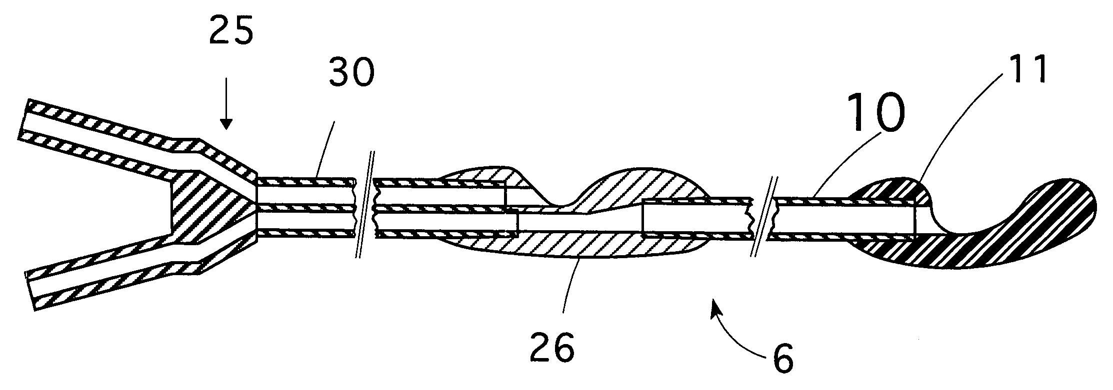
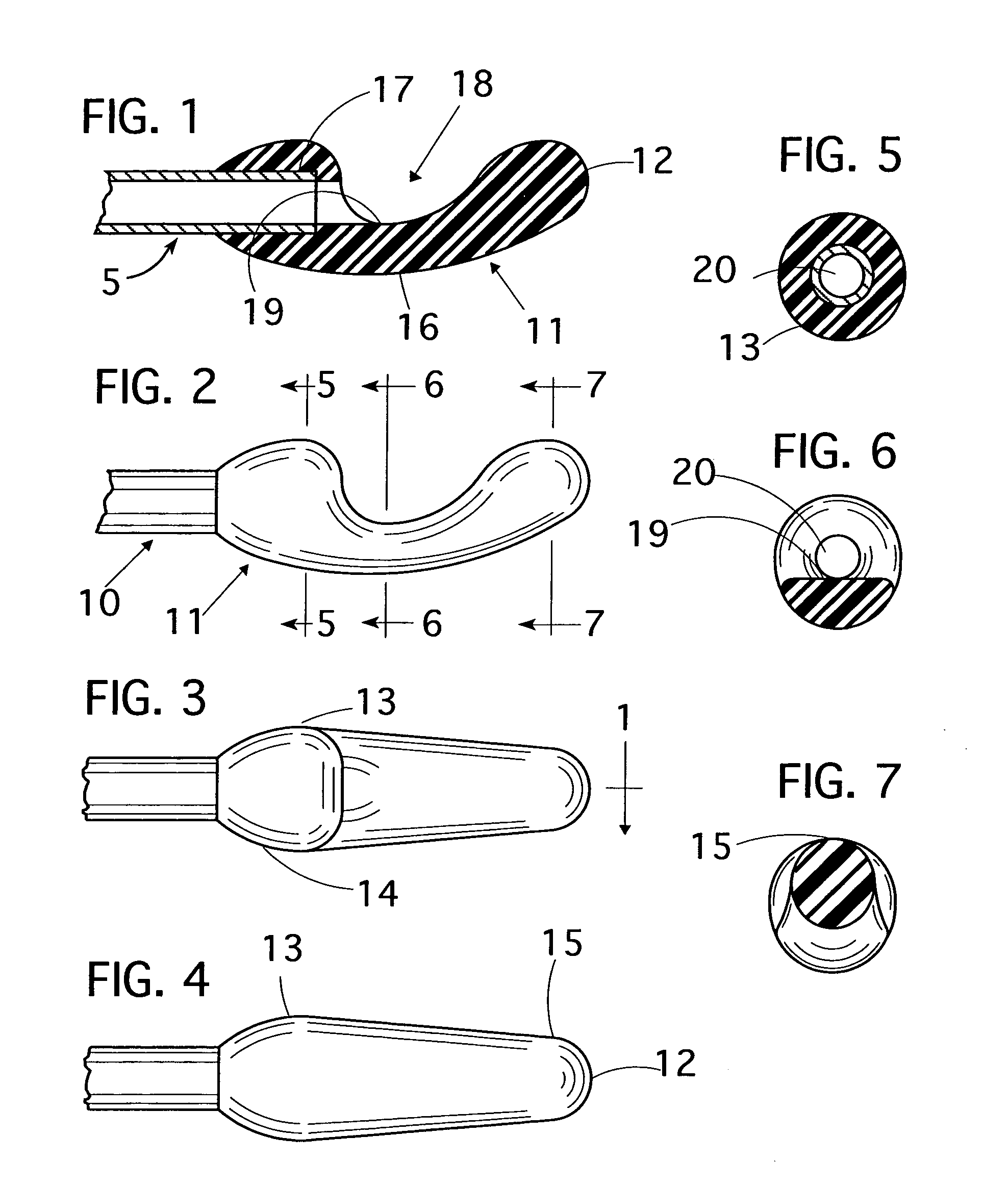
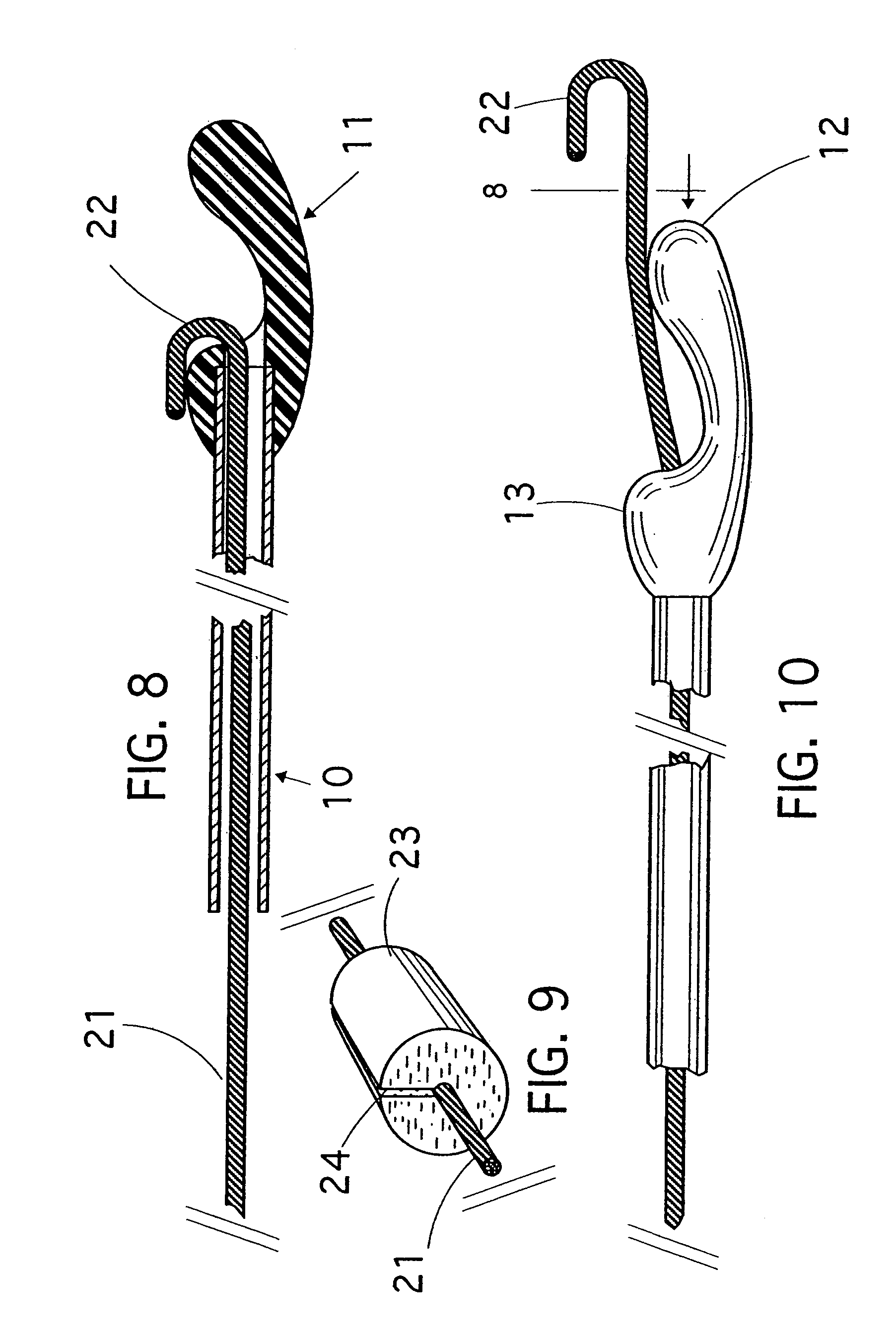
[0069]“Referring now to the drawings, and particularly to FIGS. 1 through 12, a catheter 5 embodying features of the invention includes an 8FR tube 10 shown seated in a socket 17 which extends 0.185 inches into the connector end 14 of a jejunal tip bolus 11. The OD of the bolus 11 at 13, which is shown in FIG. 5, is 0.230 inches. The OD of the bolus 11 at 15, which is shown in FIG. 7, is 0.152 inches. The bolus 11 is a “fat” bolus.”

[0070]A struture 16 in the bottom of the bolus forms an are opposite the port 18. The structural arc 16 prevents bending of he bolus toward the port, i.e., kinking, and subsequent occlusion of the port. The structural arc 16 extends 0.016 inches outside the normal maximum bolus OD of 0.230 inches.

[0071]As seen in FIG. 3, the bolus 11 tapers from its widest point at 13 to its narrowest point at 15. This taper prevents the bolus tip 12 from bending sideways out of the configuration shown in FIGS. 3 and 4.

[0072]Although, the structural arc 16 resists bending...

Login to view more

PUM

No PUM Login to view more

Abstract

An enteral feeding catheter that provides access to both the stomach and the jejunum for feeding, aspiration and decompression. The catheter includes a dual lumen “D” tube that joins to an external “Y” connector at the proximal end of the tube. The connector serves both lumens as a source for fluid or aspiration. The gastric lumen and the jejunal lumen of the “D” tube both connect to a transitional connector bolus in the stomach. The gastric lumen of the “D” tube joins with a lumen in the transitional bolus that communicates with a gastric port. The gastric port is recessed to the level of its full internal lumen, thereby providing maximum protection against occlusion and maximum area for outflow. The “D” jejunal lumen connects in the bolus with a lumen that transitions from a “D” shape to a full circle shape. The latter provides for the attachment of a smaller, round, single lumen tube that extends into the jejunum. At the distal end of the jejunal tube is a bolus containing an improved port that is also recessed to the level of the floor of the internal tube lumen to provide maximum protection against occlusion and maximum area for outflow. Both the gastric port in the transitional bolus and the jejunal port in the tip bolus include a structural arch protruding radially outwardly therefrom. The arch is effective to prevent the body segment of either bolus from bending and restricting the ports. The invention also provides for the insertion of the tube over a guidewire rather than with an internal stylet, as is normally the case with nasally inserted tubes.

Description

RELATED APPLICATION[0001]This application is based on U.S. Provisional Patent Application Ser. No. 60 / 332,678, filed Nov. 16, 2001, and claims the priority benefit thereof.FIELD OF INVENTION[0002]This invention relates generally to catheters for use in administering fluids to body cavities, irrigating the cavities and aspirating them. It relates particularly to catheters and the distal ends thereof which contain the opening(s) for fluid egress or ingress.BACKGROUND OF THE INVENTION[0003]Prior art catheter and bolus inventions are disclosed in U.S. Pat. No. 4,594,074, U.S. Pat. No. 5,451,216, U.S. Pat. No. 5,599,322 and U.S. Pat. No. 5,810,787. U.S. Pat. No. 4,594,074, for example, addresses catheter bolus construction as it relates to both aspiration and outflow. The side walls of the bolus at the bolus port are recessed to a height of no more than one half of the internal diameter (ID) of the bolus passage. Lowering the walls below this minimum level would result in bending of the ...

Claims

Login to view more

Application Information

Patent Timeline
no application Login to view more
IPC IPC(8): A61M25/00A61J15/00
CPCA61M25/09025A61J15/0073A61J15/0069A61J15/0007A61J15/0026A61M25/003A61M25/0032A61M25/007A61M2210/106A61M2210/1053
Inventor QUINN, DAVID G.
Owner RADIUS INT PARTNERSHIP
Who we serve
  • R&D Engineer
  • R&D Manager
  • IP Professional
Why Eureka
  • Industry Leading Data Capabilities
  • Powerful AI technology
  • Patent DNA Extraction
Social media
Try Eureka
PatSnap group products